Model LU-200 Beam IP65Edition EN · 04 / 2026 · V1Dokument-Nr. LU200IP-EN-01
IP65 Beam Moving Head
LU-200 Beam IP65
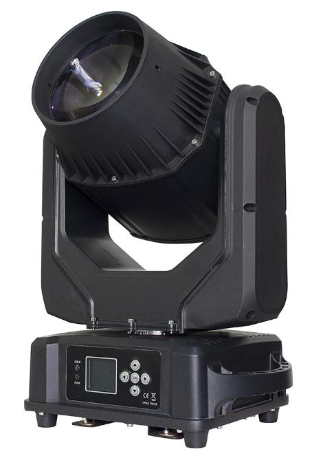
Weatherproof beam moving head with 200 W LED, 1.6° beam, 13-color color wheel, fixed gobo wheel with 17 patterns, colorful effect plate and 8+16-facet prism
Operating manual. Please read in full before first use and keep for future reference.
Light source
200 WLED
Pan / Tilt
540° / 270°+ fine
DMX channels
141 channel mode
IP rating
IP66Outdoor
Luminus LU-200 IP65 BeamForeword · About this document
Foreword
00Welcome
Thank you for choosing the Luminus LU-200 Beam IP65 — a weatherproof beam moving head with a tight 1.6° beam, a 13-color color wheel with split-color effects, a fixed gobo wheel with 17 patterns, a colorful mirror effect and a bi-directionally rotating 8+16-facet prism.
This product leaves the factory with intact performance and complete packaging. All users shall strictly comply with the warnings and operating instructions stated. Damage caused by misuse, as well as faults and problems caused by neglecting the operating manual, are not covered by the warranty. This manual is subject to technical changes without prior notice.
0.1Maintenance Notes
This fixture shall be kept dry; avoid operating it in a wet environment.
Intermittent use will effectively prolong the life of this fixture.
To achieve good ventilation and lighting effects, regularly clean the fans, fan nets and lenses.
Do not wipe the housing with organic solvents such as alcohol, to avoid damage.
Luminus LU-200 IP65 BeamContents · Overview
Table of Contents
—Overview
01Notes and Installation04
02Technical Parameters05
03Lamp Panel06
04Menu — System Settings07
4.1Calibration, Reset & System Information09
05DMX Channel Chart (14 CH, complete)09
5.1Color Wheel — Channel 0811
5.2Fixed Gobo Wheel — Channel 0912
06Common Faults12
07Notes for Use & RDM13
—CE Compliance Notice14
Luminus LU-200 IP65 Beam01 · Notes and Installation
Chapter 01
01Notes and Installation
1.1Product Precautions
To ensure the service life of the product, do not place it in a wet or leaky location, and do not operate it at temperatures above 60 °C.
Do not place the product in a location that is easy to loosen or subject to vibration.
The voltage variation of the power supply should not exceed ± 10 %. Too high a voltage shortens service life; too low a voltage affects the light color.
After a power failure, the fixture needs 20 minutes of full cooling before it can be energized again.
1.2Signal Line (DMX)
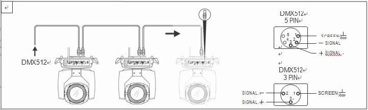
Use a specification-compliant RS-485 cable: shielded, 120 Ω characteristic impedance, 22–24 AWG, low tolerance. Do not use microphone cables or cables with different specified characteristics. Connect with 3-pin or 5-pin XLR male/female connectors (minimum ¼ W).
ImportantThe signal lines shall not contact each other or the metal shell.
1.3Lighting Installation
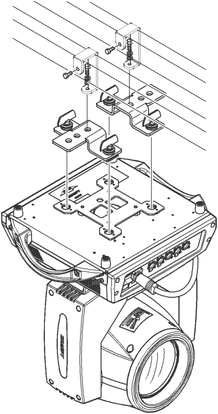
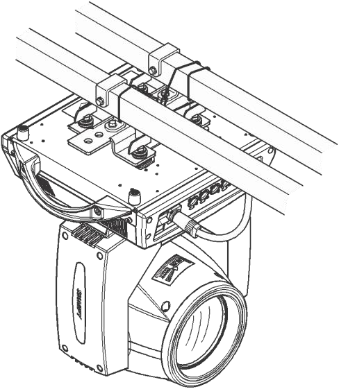
The fixture can be placed horizontally, obliquely and upside down. Pay particular attention to the installation method when hanging obliquely or inverted. Before positioning the fixture, ensure the stability of the installation site. For inverted installation it must be ensured that the fixture cannot fall from the support frame — a safety rope must be routed through the support frame and the fixture handle for auxiliary hanging, to prevent falling and sliding.
When the fixture is installed and tested, pedestrians are not allowed to pass below. Regularly check whether the safety rope is worn and whether the hook screws are loose. No responsibility is accepted for consequences caused by unstable hanging installation and the fixture falling.
Truss hanging installationInverted installation
Luminus LU-200 IP65 Beam02 · Technical Parameters
Chapter 02
02Technical Parameters
Light Source & Optics
Light source
200 W high-power LED (device manual: 150 W white LED module)
Lifespan
50.000 h
Beam angle
1,6°
Color wheel
13 colors + white light, two-way variable-speed rainbow flow effect
Pattern wheel
17 patterns + white light, two-way flow, variable-speed jitter effect
Effect plate
Colorful mirror effect
Prism
8 + 16 facet, rotatable in two directions with variable speed
2.0" LCD touch display, English/Chinese menu, shows the current fixture function
Connectors
Seetronic IP65 power IN/OUT, 3-pin Seetronic IN/OUT (5-pin optional)
Electrical & Housing
Voltage
AC 100 – 240 V, 50/60 Hz
Rated power
300 W (datasheet: 280 W power supply)
Waterproof grade
IP66 (datasheet: IP65)
Cooling
Active, with over-temperature protection
Installation
1 × omega clamp · 1 × safety attachment point
Dimensions
380 × 274 × 480 mm
Weight
10,0 kg net
Temperature and Fan ControlAt 75 °C the power drops; at 80 °C the fixture switches off directly. After the power reduction the temperature falls below 75 °C. The fan runs for 15 seconds after start-up and then regulates continuously: it engages at 46 °C and stops below 43 °C.
Luminus LU-200 IP65 Beam03 · Lamp Panel
Chapter 03
03Lamp Panel
Item
Element
Meaning
1
Signal light
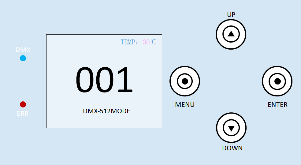
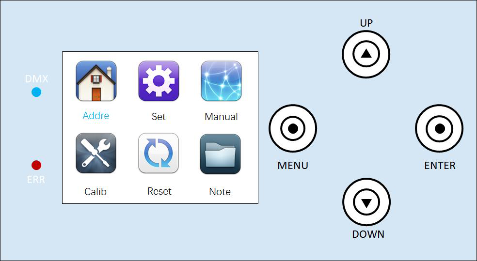
The DMX signal light is above; blue light means the fixture is connected to the console. No light is the normal condition; red light indicates a fixture error.
2
Temperature
Displays the temperature of the LED board (e.g. 30 °C). If the display shows "**°C", the temperature reading is abnormal — the temperature control line may be broken. If it shows 99 °C while the ambient temperature differs greatly, the temperature control cable may be short-circuited. Professional repair is required before further use.
3
Address code
Display range 001–512; factory setting 001
4
DMX mode
512 mode
5
Buttons
UP press up · MENU return to the previous level menu · ENTER confirm · DOWN down
Protect the DisplayNever use sharp or pointed objects to click on the display, to prevent damage.
3.1Menu First Interface
Sub-menu
Description
Address
Enter the address code setting — increase or reduce with the "UP" and "DOWN" keys; the address shown on the fixture panel updates synchronously.
Settings
System settings: change working mode, working parameters and panel display settings
Manual
Manual mode for direct control of the fixture functions — the contents correspond to the channel table
Calibration
Password-protected calibration: fixture power, motor stroke, sound control sensitivity and other parameters
Reset
System reset mode
Information
Error correction, hardware and software version and other information
Lamp panel with address displayMenu first interface
Luminus LU-200 IP65 Beam04 · Menu — System Settings (1/2)
Chapter 04
04Menu — System Settings
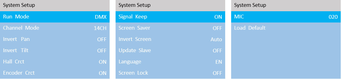
In the system settings, use "ENTER" to select the setting to be modified, select the value with "UP" and "DOWN", and confirm with "ENTER".
Option
Description
Operating mode
DMX · voice control · self-propelled 1 / 2 / 3
DMX mode
Console mode, receives DMX signal
Self-propelled mode 1 / 2 / 3
The fixture runs automatically according to the built-in self-propelled program 1, 2 or 3
Voice mode
When the fixture detects a strong sound, it automatically runs a scene according to the built-in program; otherwise it keeps the last scene
Channel mode
14 CH
Horizontal inversion
Set the X-axis rotation direction: "closure" not reversed, "turn on" reversed
Flip vertically
Set the Y-axis rotation direction: "closure" not reversed, "turn on" reversed
Hall error correction
Detects whether functions such as the gobo wheel and color wheel are out of sync and corrects them: "closure" no position correction after loss of step, "turn on" automatic correction
Optocoupler error correction
Detects whether X/Y is out of sync and corrects it: "closure" position not corrected after a misstep, "turn on" position automatically corrected
Signal hold / screen on time
"closure" screen always on, "turn on" screen turns off at regular intervals in a static environment
Screen protector
"closure" always bright, "turn on" timed screen off in a static environment
Screen flip
"closure" no reversal, "turn on" reverse display, "voluntarily" the system rotates the screen automatically according to the direction of gravity
System settingsLuminus LU-200 IP65 Beam04 · Menu — System Settings (2/2)
Option
Description
Synchronization update
Synchronizes the setting or calibration parameters of multiple fixtures. "closure" turns the function off. "turn on": after enabling, connect multiple fixtures with DMX cable and the information is updated synchronously in the setting and calibration interfaces. Note: remove the DMX signal wire connected to the console.
Language
Chinese and English menu switch ("middle" Chinese, "EN" English menu)
Screen lock
After the screen is paused it is locked. The unlock password is shown in the unlock interface prompt. "closure" not locked, "turn on" locking
MIC sensitivity
Adjusts the voice control sensitivity, range 0–255, default value 20 (0 lowest, 255 highest sensitivity)
Reset
Returns the fixture parameters to factory settings: "Cancel" keeps it as is, "confirm" restores factory settings
4.1Calibration, Reset & System Information
The calibration interface is reached by entering a password. Modify the values with the "UP" and "DOWN" keys.
Option
Description
Initial position
Adjust the initial positions of the X axis, Y axis, color plate, map plate, colorful, prism and focus motor. Range 0–255; 127 means no adjustment.
Stroke calibration
Adjust the strokes of the X axis, Y axis, fog mirror, colorful, prism and focus motor. Range 0–255; 127 means no adjustment.
Power
Adjust the maximum power of the entire fixture; 255 means maximum power.
Change password
Set the system calibration password
Reset / Information
Description
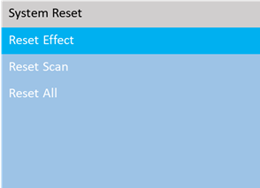
Effect motor reset
Reset of the color wheel, gobo, focus and similar motors
Scan motor reset
Only X/Y axis reset
All motors reset
Complete fixture reset
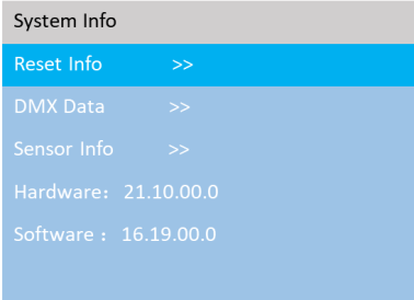
Reset error message
If the red ERR indicator lights up, the fixture is operating incorrectly: 1) IC1 communication failure (motor and display board communication failure), 2) X/Y optocoupler error, 3) motor reset failure of color disk, gobo, etc.
DMX data monitoring
Displays the channel values numerically for viewing
The LU-200 operates in a single channel mode of 14 channels. The extensive value tables for the color wheel and gobo wheel follow in chapters 5.1 and 5.2.
CH
Channel function
Value / effect
01
X axis
000–255 · level control
02
X axis fine adjustment
000–255
03
Y axis
000–255 · vertical control
04
Y axis fine adjustment
000–255
05
XY speed
000–255 · from fast to slow
06
Dimming
000–255 · from dark to bright
07
Strobe
000–003 invalid
004–099 synchronous strobe
100–149 pulse strobe
150–199 strobe
200–249 random strobe
250–255 constant
08
Color wheel
000–255 · see chapter 5.1
09
Fixed gobo wheel
000–255 · see chapter 5.2
10
Colorful
000–127 colorful cut out
128–255 colorful cut in
11
Prism
000–127 prism cut out
128–255 prism cut in
12
Prism rotation
000–127 0–400 degrees
128–190 reverse flow from fast to slow
191–192 stop
193–255 flowing water from slow to fast
13
Focusing
000–255 · 0–100 % · from far to near
14
Reset
000–199 invalid
200–205 reset all
206–255 invalid
DMX cabling in seriesLuminus LU-200 IP65 Beam05.1 · Color Wheel — Channel 08
5.1Color Wheel — Channel 08 (13 colors + white)
The manufacturer labels the color wheel positions only as "color 1" through "color 13"; no reference color chart is available. Once the real color wheel reference photo is available, this page will be updated with the actual color values.
Colour and gobo overview from the product catalogue
Note: the manufacturer channel chart lists "15–16" for pattern 4 and "19–22" for pattern 5, leaving values 17–18 undefined. Pattern 4 is given here with the gap-free range 015–018.
Luminus LU-200 IP65 Beam06 · Common Faults
Chapter 06
06Common Faults
Qualified Personnel OnlyThe fixture contains microcomputer circuit boards, a high-voltage power supply and other professional components. For your safety and the product life, non-professionals must not remove the fixture or related accessories without authorization.
Fault
Possible cause & action
Light source does not light up
The light source is not fully cooled or has reached the end of its life. Allow the light body to cool for more than 10 minutes until the internal state is fully restored, then switch on again. Check whether the light source has reached its service life and replace if necessary. Check the lamp and igniter circuit for leakage, detachment or poor contact.
The beam looks dim
Long light source usage or an unclean light path. Check whether the light source has reached its service life and replace if necessary. Check whether the optical components are clean and whether dust has accumulated — clean and maintain the light source and components regularly.
The pattern projection is vague
Check whether the electronic focus channel values are appropriate for the current projection distance.
The fixture works intermittently
The internal circuit enters the protection state. Check whether the fan is running normally or is dirty, causing the internal temperature to rise. Check whether the internal temperature control switch is closed. Check the light source and replace if necessary.
After a normal reset the console control is not accepted
Signal line failure or abnormal fixture parameter settings. Check the start address and the DMX signal line (is the signal cable intact, are the XLR connectors loose?). Add a signal amplifier and a 120 Ω terminating resistor.
The fixture cannot be started
Poor power line. Check whether the fuse on the power input socket has blown and replace it. Long-distance transport vibration may have caused poor line contact. Check the input power supply, computer board and other connecting devices.
Luminus LU-200 IP65 Beam07 · Notes for Use & RDM
Chapter 07
07Notes for Use & RDM
7.1Notes for Use
Check whether the local power supply meets the rated voltage requirements of the product and whether the residual current protector and overcurrent protector meet the load requirements.
Do not use a power cord with damaged insulation and do not attach the power cord to other wires.
The fixture uses strong forced-air cooling and therefore accumulates dust easily. It must be cleaned once a month, especially the cooling outlet; otherwise it will be blocked by dust, resulting in poor heat dissipation and abnormal fixture behaviour.
When installing the fixture, the fixing screws must be tightened and safety cables fitted; regular inspection is required.
When installing and positioning the fixture, keep a minimum distance of 10 m between any point on the fixture surface and any burning or explosive material; the irradiation distance is 2.5 m. Do not install the fixture directly on combustible material.
It is recommended that continuous operating time does not exceed 10 hours, and that the interval between consecutive starts is not less than 10 minutes; otherwise the fixture will not trigger normally due to overheating protection.
The closing time when using the shutter should not exceed 5 minutes. If the light needs to be closed for a long time, switch it off via the console (light control channel).
To ensure that multiple fixtures better comply with the scene effect, no fixture should remain permanently in an unfinished current scene while the next scene action starts — this state should not exceed 3 minutes, so that multiple fixtures can run synchronously.
If the fixture behaves abnormally during use, stop it in good time to prevent further faults.
7.2Notes for the Use of RDM
RDM is an extended version of the DMX512-A protocol — the Remote Device Management protocol. Traditional DMX512 communication is one-way; the protocol is based on the RS-485 bus, which is time-shared multi-point and semi-duplex, so only one port is allowed as host output at the same time.
Use a console or host device that supports the RDM protocol.
Use a bi-directional signal amplifier — traditional one-way amplifiers are not applicable to the RDM protocol, because RDM needs feedback data; a one-way amplifier will block the returned data, causing the fixture search to fail.
All fixtures must be set to DMX mode to ensure that there is only one host on the signal line.
A 120 Ω impedance-matching resistor must be inserted between terminals 2 and 3 of the terminating plug. With long signal lines this reduces signal reflection and improves communication quality.
If the fixture responds to DMX control but cannot be found via RDM search, first check the signal amplifier, then check whether wires 2 and 3 of the signal line have poor contact.
Luminus LU-200 IP65 Beam— · CE Compliance Notice
Appendix
—CE Compliance Notice
The manufacturer declares under its sole responsibility that the LU-200 Beam IP65 complies with the relevant EU harmonization legislation.
EU Declaration of Conformity
A signed EU Declaration of Conformity exists for this product. It is not part of this manual and can be requested from us at any time — by email to verkauf@lexvision.de or by phone on +49 (0) 651 14567727, stating the product designation.
The signed EU Declaration of Conformity for this product is available upon request from F. & M. Vertrieb GmbH, Waldweg 26, 54636 Sefferweich, Germany.